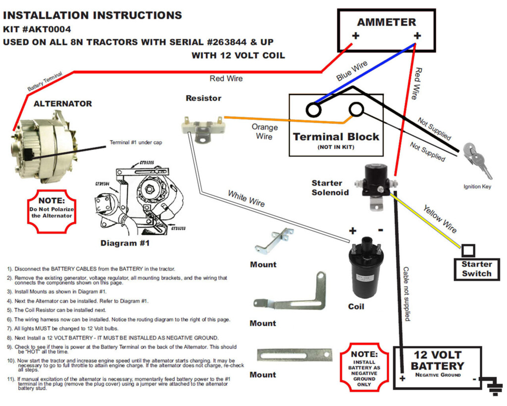
1947 8n Ford Tractor Wiring Diagram With Terminals Igntion Switch – The links in between the different parts of the ignition program are displayed on a Ford Switch Cabling Diagram. Additionally, it shows just how the ignition switch’s press process functions. The starting up port and solenoid engine, along with other important connections, are displayed within the diagram’s areas. In addition, it details the choke solenoid as well as other substantial generator elements.
ignition crucial
You need to grasp a little bit about your car’s push mechanism in order to comprehend your ignition switch wiring diagram. The connectors for the slot engine, starting solenoid, and choke solenoid should be familiar for your needs. The hyperlinks involving these elements can also be exhibited. If you don’t already have one, you can create your own wiring diagram using a program like EdrawMax.
A wire utilize must be included in the latest ignition move. Eliminate the aged one particular and link the electrical wiring utilize in the a different one to set up it. The wires and tabs in the new ignition switch should be arranged. The wires ought not to be too short and ought to be taut.
ignitor cable
The cable that starts and stops your car is known as the ignition wire. It usually has a reddish colored shade and is also coupled to the ignition switch’s “IGN” terminal. Wipers, lighting, and accessories can all be run via the cord. The links involving these elements are demonstrated inside the electrical wiring schematic for the Ford Move.
Ignition wire is 12 ga, typically. The B-G wire is connected to the Batt publish on some no-FoMoCo styles. As a result, the fuel and temperature gauges would continuously read. Thankfully, most schematics now have this problem fixed.
a dim wire
If you have any questions about the wiring configuration, always consult the wiring diagram in your Ford. It would exhibit the circuit amounts and the suitable shade for every single cable. For changing the switches, a electrical wiring schematic for a car can be helpful. The latest move will be examined using an Ohms-measuring multimeter from the following step.
You need to very first assess which terminals are connected to which switch. The change for that headlights is often orange using a black colored stripe. It is located near the steering column, typically. If the switch is working properly, the headlights will come on. If not, test the park lights.
Reddish-White-colored cable
There is a Ford-specific publication where by you can obtain a switch electrical wiring diagram. It details the color and number of each features and wire circuits that happen to be shade-coded. Additionally, a wide range of vehicle versions and yrs are protected. When you want to produce a repair yourself, this can save you efforts and stress.
The pins on your ignition move needs to be recognized, and they should be attached to the appropriate terminal. Pins are marked with the letters “BATT,” “ST,” and “IGN” (Ignition). Force-switch basic changes may be available on some cars.
Black colored-white cable
A Ford change cabling diagram exhibits the colours in the numerous circuits along with their interconnections. Diagrams for most Ford versions from distinct several years are included in this record. Ford cars within the 70s had 15-amp auxiliary circuit breakers plus a 12-amp headlight circuit. These circuits will probably be joined through the headlight switch.
It might be hard to know which wires go where by from the electric powered process of your vehicle and also in what purchase. Because of this, some Ford vehicles have color-coded wiring. By removing the need to consult manual wiring schematics for specific vehicles, this method helps to avoid confusion.
Installation technician switch
If you own a Superduty truck, you might already have a Ford Upfitter switch installed. These production line-set up changes from Ford price about $100. These changes ensure it is simple to run all of the truck’s installed add-ons, including satellite radios, stereos, plus more. In order to be installed, this switch needs to be connected to a connection C33-H that is under the driver’s seat.
The upfitter change features a relay that could management approximately 25 amps and 6 distinct auxiliary outputs. The upfitter switch may also control them, by coupling the positive wire of the spotlights to the yellow wire in the truck’s chassis.
Gallery of 1947 8n Ford Tractor Wiring Diagram With Terminals Igntion Switch