1970 Ford Neutral Safety Switch Wiring Diagram – The contacts involving the different parts of the ignition method are displayed on a Ford Move Cabling Diagram. Furthermore, it displays how the ignition switch’s push mechanism operates. The starting port and solenoid motor unit, together with other substantial connectors, are demonstrated within the diagram’s areas. Furthermore, it details the choke solenoid and other important engine pieces.
ignition important
In order to comprehend your ignition switch wiring diagram, you need to grasp a little bit about your car’s push mechanism. The connections to the slot engine, starting up solenoid, and choke solenoid must be common to you personally. The links in between these elements may also be demonstrated. If you don’t already have one, you can create your own wiring diagram using a program like EdrawMax.
A cable funnel ought to be incorporated with the new ignition change. Remove the old one particular and hook up the electrical wiring funnel in the brand new one to setup it. The tabs and wires from the new ignition switch needs to be arranged. The wire connections ought not to be short and ought to be taut.
ignitor cable
The wire that stops and starts your car or truck is called the ignition cable. It usually includes a reddish colored coloration which is linked to the ignition switch’s “IGN” terminal. Wipers, lighting fixtures, and extras can be run using the cable television. The contacts in between these elements are shown in the wires schematic for your Ford Switch.
Typically, ignition wire is 12 ga. The B-G wire is coupled to the Batt post on some low-FoMoCo themes. As a result, the fuel and temperature gauges would continuously read. Fortunately, most schematics will have this concern fixed.
a dark cable
Always consult the wiring diagram in your Ford if you have any questions about the wiring configuration. It would exhibit the two circuit numbers and the appropriate shade for every cable. For changing the switches, a cabling schematic for a vehicle can be helpful. The latest move will be analyzed employing an Ohms-measuring multimeter in the adhering to step.
You have to first assess which terminals are affixed to which move. The move to the front lights is often orange by using a dark stripe. It is located near the steering column, typically. If the switch is working properly, the headlights will come on. If not, test the park lights.
Red-White cable
There is a Ford-specific publication exactly where you can get a move cabling diagram. It databases the number and color of every features and wire circuits that are shade-coded. In addition, a large range of auto designs and many years are included. When you need to create a fix on your own, this could save you time as well as stress.
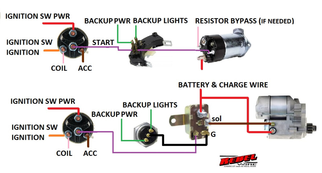
The pins on your own ignition switch has to be recognized, and they must be attached to the suitable terminal. Typically, pins are marked with the letters “BATT,” “ST,” and “IGN” (Ignition). Drive-button starter switches might be located on some autos.
Black colored-white-colored cable
A Ford move wires diagram displays the colours in the different circuits in addition to their interconnections. Diagrams for several Ford designs from different yrs are incorporated into this record. Ford autos from the 1970s got 15-amp auxiliary circuit breakers and a 12-amp headlight circuit. These circuits will be signed up with using the headlight change.
It can be tough to know which wires go in which in the electrical system of a car and then in what buy. Some Ford vehicles have color-coded wiring, because of this. By removing the need to consult manual wiring schematics for specific vehicles, this method helps to avoid confusion.
Installer move
If you own a Superduty truck, you might already have a Ford Upfitter switch installed. These manufacturing facility-installed changes from Ford cost approximately $100. These changes help it become simple to run all the truck’s installed components, which includes satellite radios, stereos, and more. In order to be installed, this switch needs to be connected to a connection C33-H that is under the driver’s seat.
The upfitter swap features a relay that can management as much as 25 amps and 6 distinct auxiliary outputs. The upfitter switch may also control them, by coupling the positive wire of the spotlights to the yellow wire in the truck’s chassis.
Gallery of 1970 Ford Neutral Safety Switch Wiring Diagram